Central Air-Conditioning Energy Saving · High-Efficiency Plant Rooms
Energy-saving retrofits for central air-conditioning plant rooms in existing buildings, covering chillers, distribution, terminals and controls. Cooling and water are supplied to match actual terminal demand, with chillers, pumps and cooling towers optimized together.
System Architecture
One system, four stages. The control platform collects operating data from each stage and regulates chillers, pumps and cooling towers as a whole.
Where Savings Come From
Industry baseline: over 90% of chiller plant rooms run below 3.5 in operating efficiency (excluding terminals), with system COP mostly between 2.0 and 3.6. Retrofits lift COP to 4–5, with most savings coming from pumps and cooling towers and only a small share from chillers.
SmartHVAC Solution
SmartHVAC has three parts: a variable-flow cooling tower system, a high-efficiency circulation system, and a high-quality system control system (the Wisdom platform).
Two-Way Variable Flow
Primary pumps run at fixed frequency to keep chiller flow constant, while terminal flow varies with load; A/B bypass valves decouple the two. See the three operating modes in the interactive diagram below.
Near Wet-Bulb Control
All cooling towers run on linked variable frequency to use the full heat-exchange area and operate near the wet-bulb temperature. See the control steps below.
Chiller Group Control
Multiple chillers are sequenced by efficiency and run preferentially in their high-efficiency range. Each 1 degree C drop in cooling-water temperature or 1 degree C rise in chilled-water temperature lifts chiller efficiency by about 3%-5%.
Water Equalizers & Variable-Flow Nozzles
Water is equalized between towers and distributed evenly across trays. Nozzles adapt to 20%–100% flow without drift or water carry-over at low flow. Fans run in their high-efficiency range at 25–42 Hz.
Reverse-Return & Low-Resistance Piping
Risers and mains use reverse-return layout with dynamic branch balancing at headers. Low-resistance filters and check valves replace pump-inlet Y-strainers, with 45° connections and no inverted-U bends.
Water Quality & Terminal Coordination
Water-quality monitoring and dosing, cooling-tower scale collectors and galvanized piping slow heat-exchange degradation. Terminal VAV and CO2-linked controls adjust fresh air to occupancy.
Modular Control Cabinets
Chiller, pump and cooling-tower control cabinets are managed together, with PLC and platform software customized per project. Balancing cabinets reserve space for balancing valves and support manual-control fallback.
High-Efficiency Plant Room Standards
ASHRAE: EER > 5.0 (0.7 kW/RT). GB 50189-2015: design-condition SCOP of at least 4.6 (excluding chilled-water pumps). The Wuhan project targets EER of at least 5.5, aiming for 6.0.
Verification Method
Functional targets are verified by measured indoor temperature and humidity. Efficiency targets are verified by third-party measurement after one month of stable operation, covering two cooling seasons, to obtain a project energy-efficiency rating certificate.
Overtime mode: the terminal bypass valve is open to maintain minimum system flow.
Cases
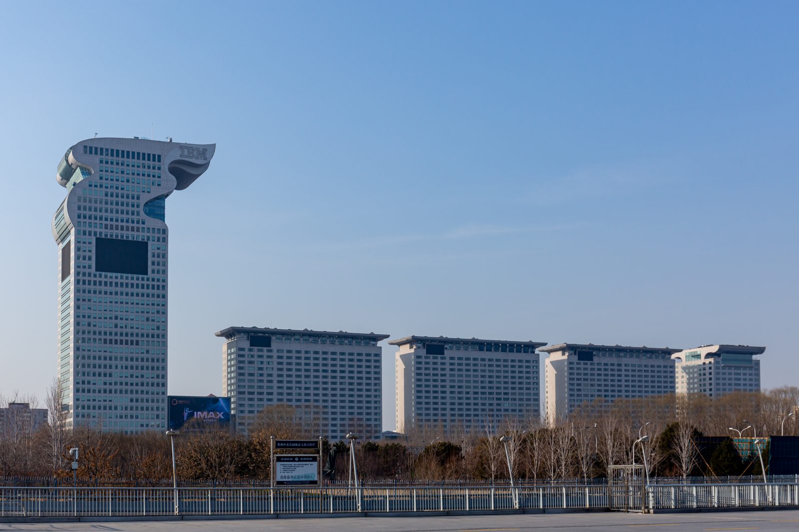
Pangu Plaza · Beijing
26.1%
Overall savings rate. Breakdown: chillers 3.4%, primary pumps 23.5%, secondary pumps 74.7%, high-rise tertiary pumps 18.8%, cooling pumps 47.3%, cooling towers 78.9%.
Chiller group controlCooling-tower variable flowPump VFD
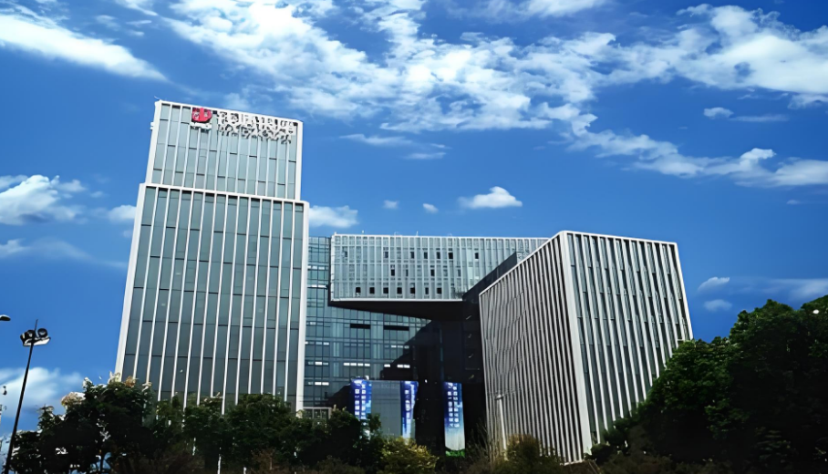
Zhongtian · Qiantang Yinzuo · Hangzhou
5.23
Full-season cumulative COP in 2021. In 2022: 474,061 kWh electricity, 2,754,294.41 kWh cooling, full-season EERa 5.81.
Plant-room group controlTerminal energy controlSub-metering
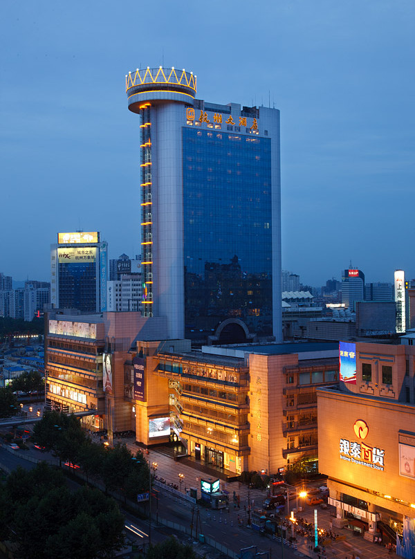
Hangzhou Hotel · Hangzhou
50.66%
Savings rate, before vs. after retrofit.
Before/after verificationSub-metering
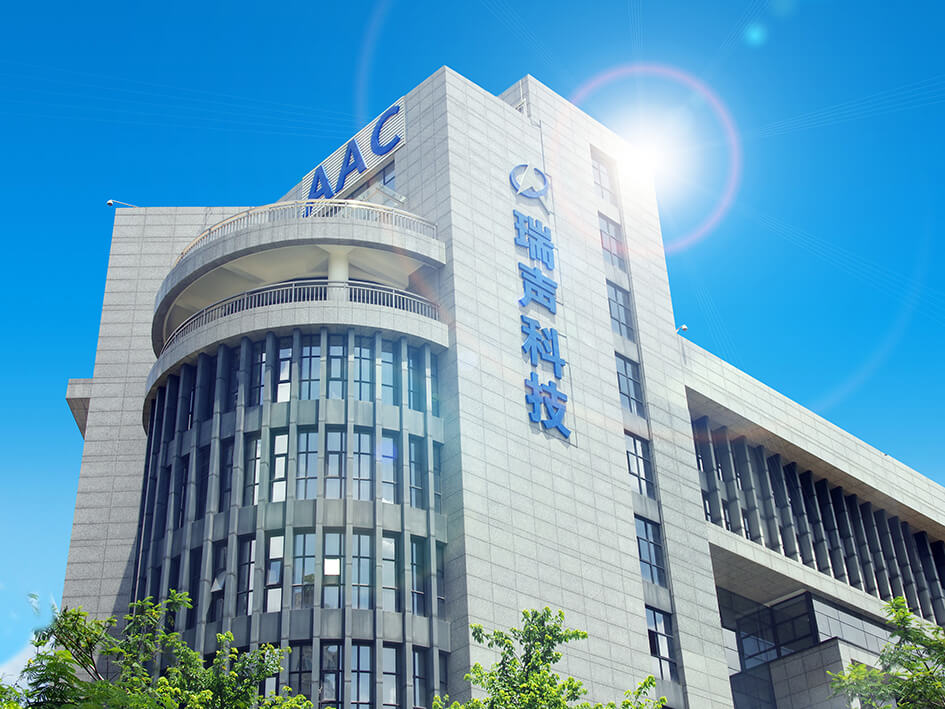
AAC Technologies
Chillers 4.6% Chilled-water pumps 43% Cooling pumps 62%
Third-party testingPump VFD
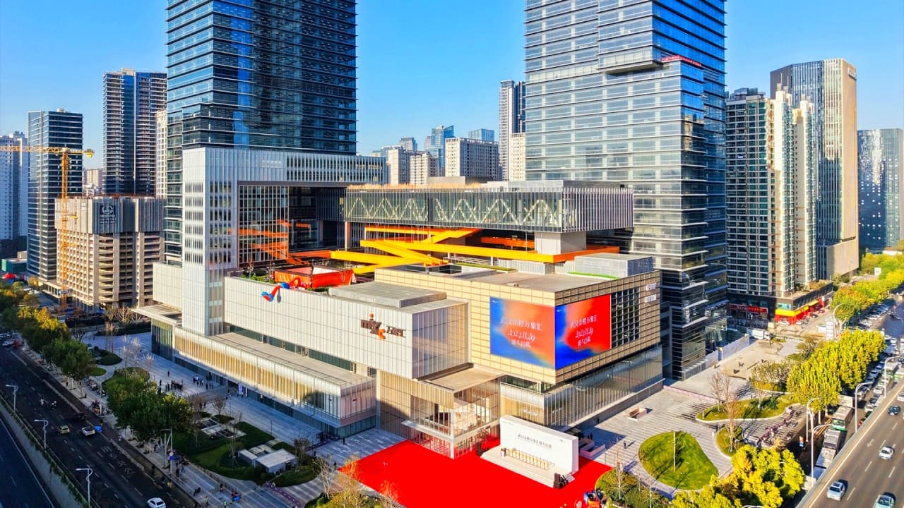
Alibaba Central China HQ · Wuhan
Cooling towers changed from 37 small-flow modules (382.5 kW) to 15 large-flow modules (330 kW), saving up to 52.5 kWh per hour; after chilled-water pump optimization, offices save about 30 kWh per hour and retail about 7 kWh per hour.
Larger tower selectionLinked VFDReverse-return pipingTwo-way variable-flow A/B valves
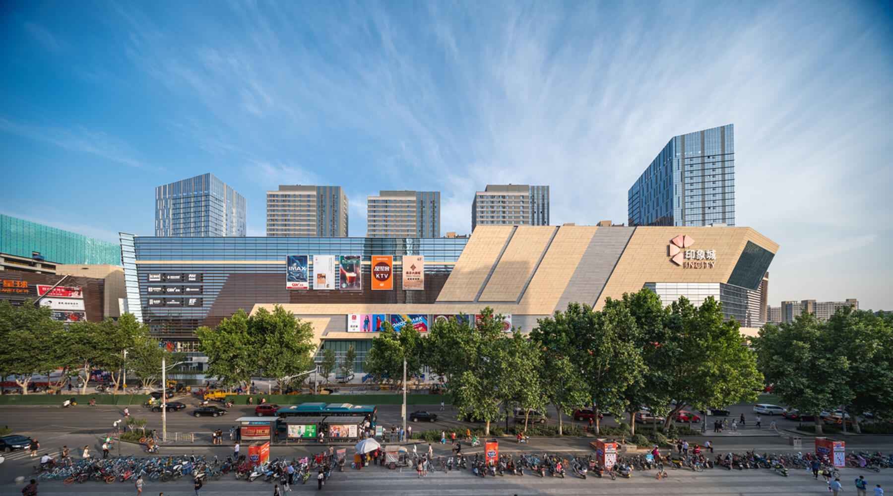
Tianjin Heping Impression City · Plant Room & Terminal Controls
Issued for construction in 2022: underground plant system drawings, building HVAC water optimization drawings, plant equipment foundation and electrical control drawings, terminal control drawings and overall topology for blocks A / B / BE / D / E, plus tender lists and high-efficiency HVAC hardware procurement schedules.
Plant system drawingsTerminal controlsBIM detailing
Energy Calculator
Estimate annual electricity saved and cost saved from total annual consumption and average tariff, using the overall 20%–35% range. A precise assessment requires the survey form and measured sub-metered data.
Cooperation Models
Four funding and management models; specific terms are subject to contract.
Client Funds All
The client funds base and energy-saving equipment and keeps all energy-saving benefits.
90% Fee · 10-Year Management
The client funds base equipment and the investor funds energy-saving equipment. The client pays 90% of the original fee each year, the investor manages the plant room for 10 years, and equipment transfers to the client at term end.
Investor Funds Energy-Saving Equipment
The client funds base equipment and the investor funds energy-saving equipment. The client pays the original fee until the agreed cumulative amount is reached, then the investor exits and equipment transfers to the client.
Investor Funds All
The client funds no equipment. The investor funds base and energy-saving equipment and manages the plant room for 10 years; the client pays 90% of the original fee each year and buys back base equipment year by year, gaining full ownership at term end.
Contact Us
Hangzhou Tianfan Energy Saving Technology Co., Ltd.
Contact: Mr. Yin Tel: 15658188166
Project survey form: ac.iesure.com This site: iesure.com